Setpoint Adjuster 0-10V
Setpoint adjuster HF10L IP66 with toggle selector switch 0-I and LED light
The new Fischbach EC-speed controller HF10L IP66 convinces not only with the robust design and the high protection class IP66, but above all with its sophisticated concept of multifunctional operation in the field of professional kitchen exhaust air. The additional blue illuminated LED switch can be used for lighting of the kitchen hood or even other consumers. Thus, the further attachment of bulky wet room surface- mounted switches with a lower degree of protection is unnecessary.
Benefit from the new HF10L IP66
- compact design
- integrated LED light switch
- robust processing
- high degree of protection IP66
- with high quality potentiometer 0-10V – high stock availability
- low installation costs
- suitable for all EC Motors
Setpoint Adjuster HF10F IP66 with LED toggle switch and LED indicator light
Fischbach setpoint adjuster HF10F IP66 with blue LED toggle switch 0-I and additional yellow LED indicator light contains a 10 kOhm potentiometer for controlling devices with 10V output or 0-10 V control input, as well as an additional switching contact for valves etc. Robust, impact-resistant surface-mounted housing, protection class IP66.
Download Material
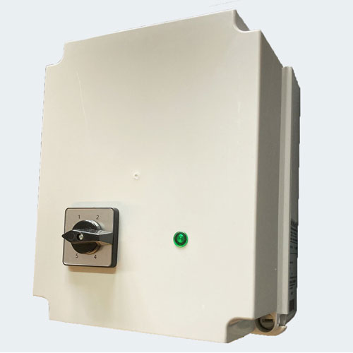
Setpoint adjuster HF10 IP66 with toggle selector switch 0-I
The Fischbach control unit HF 10 IP 66 with toggle selector switch 0-I includes a 10kOhm- setpoint adjuster for controlling units with 10V-output and 0-10V control input, as well as an additional switching contact. Solid, impact-resistant surface-mounted casing, protection class IP66 for use in industrial and kitchen areas.
Download Material
Centrifugal Fan Speed Controller FDR-B
Fischbach Speed Controller were constructed to control the speed of the disc-rotor-motors for the best operating point in fans, fan units or AHU (air handling units).
Stepwise: Voltage adjustment by step switch (5 steps and 0-setting).
In casing: Complete ready for wiring with integrated contactor, on/off keys, motor overheating protection via thermal contacts in motor, secondary fuses or in case of types FDR 20/3 instead of fuses one or two motor protections relays adjustable according to the nominal current of the motor or each stator of double motor.
Without casing: Just a tranformer with labeled connections.
Operation and function: Operation of the fan is via step switch of the speed controller. The controller is interlinked with the thermal contacts in the fan motor. For motor overheating the thermal contact will switch the speed controller off (also the lamp). When operating the indicator light glows. Should the fan stop due to power failure, open thermal contacts, etc. the indicator light will extinguish.
The stepwise speed controller, FDR-B have an potential free contact (clamp 1-2).
Connection of an electromagnetic valve or relay is possible.
Download Material
Dimensions stepwise
Connection stepwise
Assignment
Speed Controller FRE-B
The FRE-B speed controllers are designed for speed control of single-phase fan motors. The output voltage is controlled via a potentiometer built into the housing or an external 0-10VDC signal. Control is by phase angle control.
- voltage (PRI): 1x230V
- frequency: 50/60Hz
- max. current: 3A, 5A or 10
- protection grade: IP44
- isolation class: II
- control: potentiometer or 0-10VDC signal
- conformity to: EN55032, EN 55035, EN IEC 61000-3-2, EN 61000-3-3, EN IEC 62368-1
Download Material:
Speed Controller Frequency Inverter FFU
Frequency inverter E800
The drive E800 is the latest generation of devices, developed for global use to cover all applications of electrical drive technology, from simple speed control to complex machine control.
Frequency Inverter EM30 IP66 (jet water protection)
The drive EM30 convinces with its high degree of protection IP66 (jet water protection) + NEMA4 ( shock proof 4G) and is thus perfectly suited for use in rough conditions (outside areas, kitchens, etc.).
Speed Controller F-AC
Regulation
By default, the F-AC0.5 is driven on a slip torque/speed curve that allows, for example, a partial compensation of filter pressure drops. The F-AC0.5 controller is separated from the motor; case of a defective motor, the controller can be maintained, and vice versa. With separate placement of our regulator the high protection class of the motor (IP65) is retained and also the high fan inlet air temperature.
Speed Controller F-AC 0.5
The Fischbach-Controller F-AC0.5 is designed for speed control / regulation of Fischbach motors. The speed can be set with a remote set point device (potentiometer), or with an external 0 – 10V control signal. The Controller F-AC0.5 has a + 10V – power supply for external devices. For the START / STOP function additional connections are not required, since this function works directly with the 0 – implemented control voltage – 10V. If the input voltage is less than 1V, the device is located in a STOP condition (is in STOP state). As soon as the control voltage 1V has overrun, followed by the positioning of the rotor, the start controller and the engine speed is proportional to the input signal. Due to the sensorless operation the motor cable only consists of the two phases and two wires for thermal contact.
The two LED’s show the engine state or error messages are displayed. (see function tables in the assembly instructions). The disc rotor motor is electronically commutated by the F-AC0.5 in two phases. There is no need for an operating capacitor – phase shifting is electronically controlled. The controller operates sensorless, the rotor position is detected and calculated by a special processor in accordance with the motor voltages.
The second processor is responsible for the following protection functions:
- Motor temperature monitoring (shutdown at over temperature)
- Current monitoring of the motor (switched off for overcurrent)
- Mains voltage monitoring (shutdown with overvoltage / under voltage)
- Voltage drop, or fast on / off switching in succession (loose contact)
- Temperature monitoring of the controller
Technical specification:
Mains voltage required: 1x230V
Max. electrical power: 750W
Max. current: 6,0A
Protection class: IP54
Max. ambient temperature: 35°
Control:
Control signal: 0-10V (or set point device)
Max. current: 10mA
Power supply: 10V
Max. current: 20mA
Dimensions: 120 x 105 x 85mm
Download Material
Speed Controller F-AC 1.5
Speeds of up to around 2000 rpm can be achieved depending on the motor and fan operating point. Once the fan has been installed, an auto-tuning function is started, which saves the data for controlling the motor accordingly.The product release of the extended version F-AC 1.5 is expected in 2025 and will bring significantly more power and additional features.Questions & suggestions?
Your feedback is welcome.
EC Controller F-EC
Regulation
By default, the EC- regulator is driven on a slip torque/speed curve, as in the standard (AC) disc rotor motor, for example, allows a partial compensation of filter pressure drops. The EC controller is separated from the motor; case of a defective motor, the controller can be maintained, and vice versa. With separate placement of our regulator on the housing of the fan, the high protection class of the motor (IP65) is retained and also the high fan inlet air temperature.
EC Controller F-EC 0.5
The Fischbach – EC Controller is designed for speed control / regulation of Fischbach EC motors. The speed can be set with a remote set point (device (potentiometer), or with an external 0 – 10V control signal. The EC Controller has a + 10V – power supply for external devices. For the START / STOP function additional connections are not required, since this function works directly with the 0 – implemented control voltage – 10V. When the input voltage is less than 1V, the device is located in a STOP condition (is in STOP state). As soon as the control voltage 1V has overrun, followed by the positioning of the rotor, the start controller and the engine speed is proportional to the input signal. The sensor less operation is the motor cable only from the three phases and two wires for thermal contact.
The two LED’s show the engine state or error messages are displayed. (see function tables in the assembly instructions). The EC-disc rotor motor is electronically commutated by the EC Controller in three phases. The controller operates sensor less, the rotor position is detected and calculated by a special processor in accordance with the motor voltages.
The second processor is responsible for the following protection functions:
- Motor temperature monitoring (shutdown at over temperature)
- Current monitoring of the motor (switched off for overcurrent)
- Mains voltage monitoring (shutdown with overvoltage / under voltage)
- Voltage drop, or fast on / off switching in succession (loose contact)
- Temperature monitoring of the controller
Technical specification:
Mains voltage required: 1x230V
Max. electrical power: 750W
Max. current: 6,0A
Protection class: IP54
Max. ambient temperature: 35°
Control:
Control signal: 0-10V (or set point device)
Max. current: 10mA
Power supply: 10V
Max. current: 20mA
Dimensions: 120 x 105 x 85mm
Download Material
Controller F-EC 1.5
Speeds of up to around 2000 rpm can be achieved depending on the motor and fan operating point. Once the fan has been installed, an auto-tuning function is started, which saves the data for controlling the motor accordingly.The product release of the extended version F-AC 1.5 is expected in 2025 and will bring significantly more power and additional features.
Questions & suggestions? Your feedback is welcome.